Online Digital Forensics Courses and Labs
Building a Low-cost and State-of-the-art IoT Security Hands-on Laboratory
Funded by National Science Foundation (NSF)
Funded by Cyber Florida
IoT Secure Key Storage Lab
Instructor: Bryan Pearson, 386-882-1360, bpearson@knights.ucf.edu
Prerequisite:
- Some basic knowledge of Linux and the Bash terminal
Goals of this tutorial:
In this tutorial, the student will learn how to use the secure key storage capabilities of IoT devices. The ESP32 will be used in this lab. The student will first learn how to communicate and program the ESP32. Then they will learn how to perform a physical readout of the flash and steal WiFi credentials in the firmware. Finally, the student will learn how to enable flash encryption and protect the firmware against attacks.
Overview:
- Student will learn about the secure key storage capabilities in the ESP32.
- Student will learn how to perform a physical readout of the ESP32 flash and identify sensitive data in the firmware.
- Student will learn how to enable the flash encryption of the ESP32 by leveraging the secure key storage.
Hardware Needed:
- USB A to Micro USB
- An ESP32 development board, such as the ESP32-DevKitC. Can learn more here.
Software Needed:
- Ubuntu 20.04 disc image (ISO)
- VirtualBox
- ESP-IDF version 4.1: ESP-IDF is a framework for ESP32 that comes with all necessary software, including the compiler toolchain and various tools for programming and inspecting the ESP32's secure key storage.
- Lab materials, including a pre-configured VM image with all the necessary software, can be downloaded from here.
Environment Setup:
Setting up the Virtual Machine:
Download the VM image from the lab materials link. Once it finishes downloading, you need to import it into VirtualBox. In VirtualBox, click on File → Import Appliance. Select the downloaded image. Click Next, then Import. After a minute or so, the VM will appear on the left side of the window, as shown below:
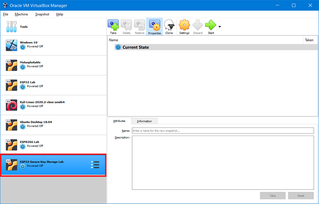
Figure 1: VirtualBox manager; imported VM is shown in bottom left.
You can also click Settings to modify the VM before booting it up. By default, it will use 8 GB of RAM and 2 CPU cores, so change these settings to suit your environment. Once you are done, click Start to boot up the machine.
Verifying the Setup
First, log into the machine. The username and password are esplab:esplab. Then click on the terminal icon on the left side of the screen. If all goes well, you will be greeted with the following message, indicating that the development environment is successfully installed:
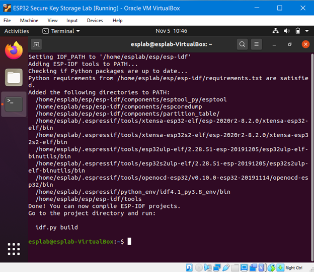
Figure 2: Terminal greeting which indicates that ESP-IDF is successfully installed.
Setting up the Serial Port
Now we will verify that we can program and monitor our ESP32. First, we need to install the necessary drivers. Most ESP32 boards will contain a CP210X chip which allows data transfer between UART (used by the ESP32) and USB (used by the cable). However, communicating with this chip, and therefore the ESP32 itself, requires the correct drivers to be installed on your computer. You can download the CP210X drivers to your host machine from here.
Now, plug the ESP32 into your computer. You can confirm that the driver was installed correctly by navigating to Devices → USB in your VM window. You should see a device such as ``Silicon Labs CP2102 USB to UART Controller''. Click this button in order to enable communication between your VM and the ESP32.
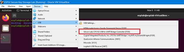
Figure 3: Identifying the USB port inside your VM.
Running the Example Application
Now we will run the example ``hello_world'' application for the ESP32, located in the following directory: /home/esplab/esp/workspace/hello_world. In your terminal, navigate to this directory. Now run:
This will compile the application. The compilation will take a moment to complete. If all goes well, you will be greeted with a ``Project build complete'' message and a command to upload the firmware to the ESP32, as shown below:
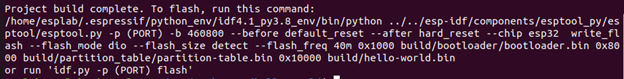
Figure 4: Output for successful project build.
To upload the compiled firmware to your board, run:
A common error you may see at this point is ``RuntimeError: No serial ports found,'' which occurs when the framework cannot identify the ESP32 serial port. You can find this serial port yourself by running:
This should return a file such as ``/dev/ttyUSB0''. If you see this file, then rerun the command as:
If you do not see this file, that means your VM cannot see the ESP32. Double-check to ensure that the USB-to-UART driver was successfully installed. Another possibility is that your ESP32 board contains a different serial-to-USB chip than the CP210X. In that case, you should consult the documentation for that board to identify the correct chip and download the appropriate driver.
If the flash command works, you will see that the firmware will upload to the board, as shown below:
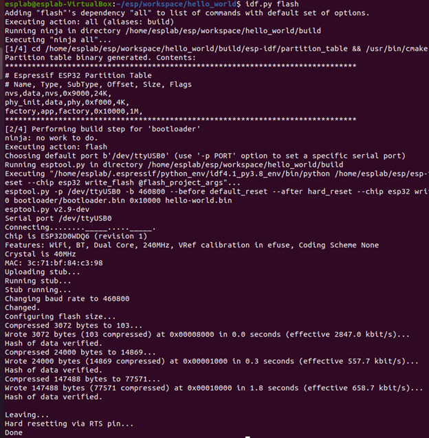
Figure 5: Output for successful flash command.
To monitor output from this application, run:
Or:
This application prints ``Hello world'', various information about your particular board, and resets after 10 seconds.
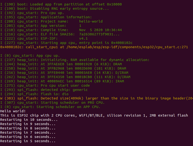
Figure 6: Hello World application (and bootloader) output.
To exit this monitor, press Control + ].
Viewing the Secure Key Storage
The ESP32's secure key storage is managed by a 1024-bit eFuse memory region, subdivided into 4 blocks of 256 bits each. Block 1 and Block 2 are used for secure key storage; Block 1 stores a flash encryption key, while Block 2 stores a Secure Boot key. Block 0 is used to configure the ESP32, while Block 3 can be defined by the programmer. In this lab, we will focus on Block 1 (flash encryption key) and some contents in Block 0 which affect the flash encryption behavior.
To view the eFuse memory contents, simply run:
This will print the identifier, description, value, and read/write permissions of each eFuse. You should see output similar to below:
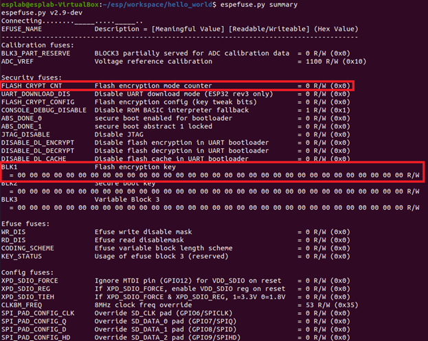
Figure 7: eFuse memory contents before flash encryption is enabled.
The FLASH_CRYPT_CNT and BLK1 eFuses are most important to flash encryption. FLASH_CRYPT_CONFIG is also important as it affects the behavior of the encryption algorithm. For more information on this algorithm, see here.
Physical Attack:
Running a Sensitive Application
Now we will run a more sensitive application on the ESP32 and show how credentials can be stolen off the device when flash encryption is not enabled. Download the zip file wifi-station-example.zip from the lab materials webpage, then extract into your workplace directory. Navigate to the new station project folder and run:
This will open a configuration window. You can use the arrow keys to navigate to each option, press enter to enter a sub-menu, and press escape to leave a submenu. The controls are also shown at the bottom of the window.
Navigate to the Example Configuration menu and enter your WiFi SSID and password. (For context to my screenshots, I have opened a mobile hotspot on my machine and set the SSID to esplab-hotspot and password to ilovebagels.)
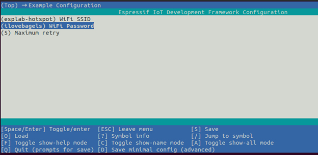
Figure 8: Setting the WiFi credentials in the project configuration program.
Press escape to return to the main menu, then escape again to quit. You will be prompted to save the changes. Press Y to confirm. Now run:
This will build, flash, and monitor your application all in one command. In the serial monitor, you should see that the ESP32 was able to successfully connect to your WiFi network.
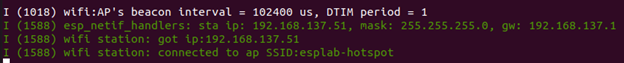
Figure 9: WiFi Station application output.
Stealing WiFi Credentials
Now we will assume the role of an attacker who has just gained physical access to the ESP32 and wants to discover the WiFi credentials in the flash. We will soon see that this is all too simple.
First, download the firmware from the ESP32:
This will copy the ESP32's flash contents in the address range 0x10000 - 0x20000 into a file named flash_contents.bin.
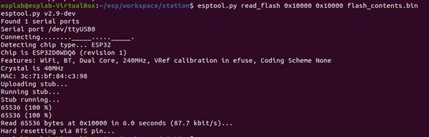
Figure 10: Read flash output.
Now run:
Replace {SSID} with your network SSID. You should see the SSID return in red text and password immediately after.

Figure 11: Finding WiFi credentials in the firmware.
Defense Against the Physical Attack:
Generating the Flash Encryption Key
Now we will defend against the physical attack by encrypting the firmware. First, generate the flash encryption key:
A flash encryption key will be generated and stored in the file flash_encryption_key.
Enabling Flash Encryption
Now we will store the key in eFuse Block 1. Run the command:
This will prompt a warning informing you that the operation is irreversible. This is due to the OTP (one time programmable) nature of the eFuses. Type BURN to continue on and wite the key into the block.
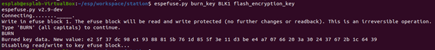
Figure 12: Setting the flash encryption key.
There are a few other actions needed to enable flash encryption. Open the project configuration menu:
Navigate to the Security Features menu and enable the option "Enable flash encryption on boot." Make sure that the usage mode is set to Release, not Development. These settings will ensure that the bootloader is compiled to support flash encryption. Now save your configuration (hit escape a few times, followed by Y to save your changes).
Running an Encrypted Application
Build and upload the firmware to your ESP32, and open the serial monitor:
Before running the application, the bootloader will detect that flash encryption has been enabled. It will prompt the chip to set the corresponding eFuses in Block 0 and encrypt our application, which starts at flash address 0x10000. This encryption step will take a minute or two, so be patient. Do NOT interrupt the power flow or serial monitor, or you may corrupt the device.You will see output resembling the following:
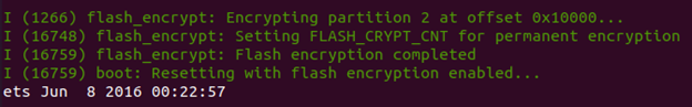
Figure 13: The bootloader encrypting the firmware.
When this completes, the device will reboot and run your application, just like before. However, the firmware stored inside the flash region is now encrypted.
Now exit the serial monitor and take a look at the eFuse summary again:
You will see that FLASH_CRYPT_CNT and BLK1 have been modified.
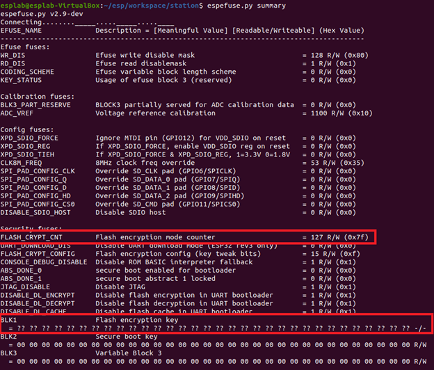
Figure 14: eFuse memory contents after flash encryption is enabled.
FLASH_CRYPT_CNT informs the ESP32 whether or not flash encryption is enabled. It is a 7-bit field, meaning its highest value is 127. If an odd number of bits are set to 1, then flash encryption is enabled. Otherwise, flash encryption is disabled. Based on the value of FLASH_CRYPT_CNT, which is 127 (i.e., all 7 bits are 1), we can see that flash encryption is enabled. Furthermore, eFuse bits are OTP (cannot be changed from 1 to 0, only from 0 to 1). Therefore, FLASH_CRYPT_CNT cannot be changed from the value 127. This means flash encryption cannot be disabled.
BLK1 hides the true value of the flash encryption key due to the secrecy of that data. However, the output (= ?? ?? ... ?? ?? -/-) indicates that the key was stored successfully and cannot be read or modified. Trying to write a new key into Block 1 results in an error:
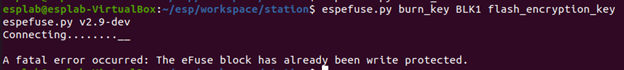
Figure 15: Burn key error.
Verifying the Defense
Now we again assume the role of an attacker. Download the firmware from the ESP32:
When the download completes, try to find the SSID and password again:
You will find that this command does not return any output (if it does, you did not enable flash encryption!). That means that our WiFi credentials are safely protected by the flash encryption key, which in turn is protected by the secure key storage.
Uploading New Firmware
The bootloader will only perform the encryption operation once, so uploading another plaintext firmware will result in soft bricking the device, because the ESP32 will assume flash contents are encrypted and attempt to transparently "decrypt" this content before it reaches the processor.
Let's try to upload the ''hello_world`` application again. Navigate to the hello_world project directory and run:
You will see a ``flash read err'' indicating that the firmware cannot be read by the processor.
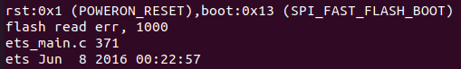
Figure 16: Flash read error.
However, since we pre-generated the flash encryption key which is stored in eFuse Block 1, we can encrypt the firmware before uploading it to the board. Copy the flash encryption key into the current directory. Then run the following commands:
In order, each command:
- Encrypts the bootloader
- Encrypts the partition table, which points to the starting address of the firmware
- Encrypts the firmware
- Uploads the encrypted files to their appropriate addresses in the flash
- Opens the serial monitor
You will now see the ``hello_world'' application running now without any errors. This method shows that as long as you have the pre-generated flash encryption key, you can always upload new firmware to the ESP32.
Decrypting the Firmware
Return to the WiFi station project in the Station directory. Recall that the file flash_contents.bin contains our encrypted firmware from the ESP32. Run the following command to decrypt this firmware:
This will use the flash encryption key to decrypt the firmware and store the plaintext version in the file ``flash_contents_decrypted.bin''. Now try to find the SSID and password in this new file:

Figure 17: Finding WiFi credentials in the decrypted firmware.
It is for this reason that in a true production environment, the flash encryption key should never be pre-generated. An attacker who can gain access to this key will have the capability to fully decrypt the firmware on your device. Instead, the flash encryption key should be generated by the ESP32 itself. This actually would have occurred if we had not pre-generated the key beforehand; the bootloader would have signaled the chip to generate the key, and it would have never left the chip.
Take Away:
In this lab, the student:
- Programmed and communicated with the ESP32
- Observed the secure key storage of the ESP32
- Performed a physical readout of the ESP32 flash contents
- Stole WiFi credentials from a firmware
- Enabled flash encryption on the ESP32
- Uploaded new firmware after flash encryption was enabled
- Decrypted the firmware using the pre-generated key